

OEM Motorized Regulating Valve Selection Tips for Reliable Flow Control
2026-11-23
Flow control looks simple until a motorized regulating valve that worked in one OEM system starts hunting, sticking, or drifting in another. The difference is rarely the motor itself—it is how the valve was specified. Below, we share practical selection tips that can help you avoid unstable control and premature wear, with field-informed insights from HONGSEN to guide your next specification.
Forget the Catalog Flow Coefficient for a Minute
Most sizing routines start with a clean number pulled from a brochure, but that figure only holds up on a test bench with long straight runs and tightly controlled conditions. Walk out to the actual pipe rack and the same valve suddenly behaves differently because the flow entering it is already disturbed by elbows, reducers, or a half-open isolation damper just upstream.
Instead of treating the published coefficient as a fixed property, it helps to think of it as a starting point that gets eroded by real geometry and operating conditions. Viscosity, choked flow, cavitation, and even the direction of installation can shift capacity enough to make the catalog value misleading. Once you accept that, you stop forcing every selection into a textbook equation and start looking at the whole assembly.
A quick field check often reveals why two “identical” valves perform nothing alike. One may be tucked behind a tight bend while the other sits in a generous straight section. That difference rarely shows up on the datasheet, but it shows up in flow, noise, and wear. So before trusting the number, spend a little time on what surrounds it.
Your Fluid Is Harder on Valves Than the Datasheet Admits
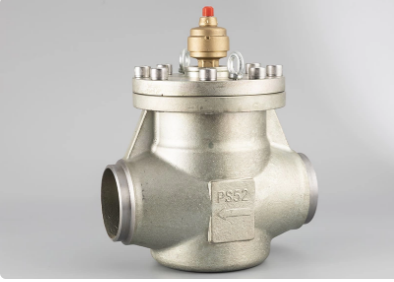
A datasheet assumes your fluid is polite. It quotes flow coefficients from clean water, a tidy pH range, and steady temperatures. Real lines don't run that way. Fines scour seats and stems long before the rated cycle count. Salts precipitate during temperature swings and tighten clearances until every stroke needs more air. The Cv curve never hints at any of that.
Cavitation gets a footnote, but in the field it eats plugs and cages in weeks. Even a modest pressure drop can collapse vapor bubbles right past the throttle point, hammering metal until packing leaks and the actuator can't hold setpoint. The valve hasn't failed on paper. It just stopped doing its job.
Material charts are just as optimistic. They test a clean fluid, not the trace solvent someone added in a wash cycle, or the air slug that arrives on a cold start. Soft seals usually lose to the additive nobody listed on the purchase order. A datasheet is a starting point, not a field report.
Low Flow Is Where Regulating Valves Show Their True Character
Most valves handle full-open or full-shut duties without much drama. It is only when flow drops to a trickle that the real test begins. Metal seats, soft seals, and trim geometry all behave differently as the gap narrows. A valve that throttles smoothly at 60% travel can suddenly chatter, sing, or erode at 10%. This is where precision, not just pressure rating, decides whether the process stays stable.
At low flow, regulating valves reveal how well their flow characteristic matches the system. Equal percentage and linear trims stop being catalog terms and start shaping control loop behavior. Cavitation and flashing also turn vicious here because the pressure drop concentrates across a tiny opening. Hardened trim, anti-cavitation cages, and careful sizing become non-negotiable. Without them, the valve may still open and close, but it will never truly regulate.
Field technicians often judge a valve by how it behaves when barely cracked open. Slight stick-slip, minor seat leakage, or unstable positioning that goes unnoticed at high flow becomes obvious at low flow. The best regulating valves are not the ones with the highest Cv or the widest range on paper. They are the ones that hold a setpoint without hunting when the demand is almost nothing, hour after hour.
The Motor and Valve Pairing Deserves More Than a Quick Check
A glance at rotation and a quick listen for chatter will tell you something, but not much. When a motor and valve have been running as a pair for years, their real condition hides in the overlap between torque curves, seat wear, and the way the actuator loads up just before closing. That relationship shifts long before an operator notices a fault.
Take a modulating valve that only gets exercised during shutdowns. The motor may still spin freely on the bench while the valve stem starts binding under pressure, or the coupling may be taking a beating that no static inspection would reveal. Checking the pairing means running it through part-stroke moves, not just confirming full open and full close, and paying attention to how long the last ten percent of travel takes.
Trending those details changes the conversation from “is it working today” to “where is it heading next quarter.” Vibration readings, current draw at the seat, and even slight changes in closing time give a much earlier warning than a pass/fail glance. The pairing deserves that extra attention because most failures don’t start with a bang; they start with a small change someone decided wasn’t worth writing down.
Feedback Signals Are the Difference Between Control and Guesswork
Control only works when the system knows what it is actually doing. A command that sets a target is not control by itself; it is an intention. The difference shows up in the return path. Feedback brings back a measured result, compares it with the target, and turns the gap into the next adjustment. Without that loop, every action is based on an assumption about how the process might respond, which is closer to guesswork than to regulation.
A thermostat makes the distinction plain. The setpoint tells the heating system where the room should be, but the sensor reading tells it where the room is now. Those two pieces of information meet in the controller, and the difference drives the output. Cut the sensor wire and the same algorithm keeps running, yet it no longer controls anything. It just sends commands into the dark, hoping conditions happen to match the model.
The same pattern holds in larger systems, from automated warehouses to chemical reactors to robotic motion. Small mismatches never stay small for long when they are ignored. With a live error signal, corrections happen early and often, so the process stays inside its operating envelope. Without it, operators lean on estimates and historical patterns until drift becomes a surprise. Feedback is what turns a plan into a closed loop instead of an open bet.
Ask the OEM to Prove Performance on Your Actual Process
A spec sheet or a polished webinar means little until the equipment has run against your actual slurry, viscosity, solids loading, temperature swings, and shift-to-shift variability. Ask the OEM to bring a pilot unit or run a trial on a slipstream of your process, not a bench-top setup with tap water. During the run, have them record pressure drop, wear, energy draw, seal behavior, and any cleaning or clogging events under your normal operating window.
The most useful proof is not a curated summary. Ask for raw trend data, photos of worn parts after the trial, and a clear list of what failed or needed adjustment. If they keep pointing to a reference site with a different chemistry, ask how that site maps to yours. A capable OEM will welcome a narrow test protocol that targets the two or three failure modes that actually cost you time and money.
Pay attention to how the performance claim converts into plant-level outcomes: yield retention, downtime, scrap, cleaning cycles, maintenance hours. Let them show the math on your process, not on an idealized case. If the data stays vague or the trial keeps getting postponed, that hesitation is information. You are not looking for a demonstration; you need enough evidence to make a capital decision.
FAQ
Start with the required Cv at minimum, normal, and maximum flow, not just the peak condition. Then check how much inlet pressure swing the system will see. A good target is to have normal flow land between roughly 20% and 80% of stem travel so the valve has usable modulation range in both directions.
Valve authority affects how the installed flow characteristic behaves. If authority drops much below 0.3, the valve tends to act more like an on-off device and the loop can start hunting. Keeping authority between about 0.3 and 0.7 usually gives stable, predictable modulation.
Look at continuous torque at the maximum pressure drop, not just breakaway torque. Check the motor duty cycle and thermal class because stalled or slow movement under load can overheat a marginal actuator. Also consider backlash and response time if the loop demands small, frequent position changes.
A practical approach is to offer 4-20 mA with HART as a base because it fits most process control systems and supports basic diagnostics. Add 0-10 V for lighter commercial or lab setups, and Modbus RTU or TCP when the equipment needs tighter integration without extra wiring. Avoid forcing a single bus protocol unless the application clearly requires it.
Select hard trim materials, use a characterized cage or guided plug to handle the flow conditions, and keep velocity within the trim rating. In some designs, self-flushing passages or purge ports help keep solids from packing around the seat. Slowing the stroke slightly can also reduce erosion and water hammer.
The fail-safe action should come from the process risk review, not from a default catalog choice. If the actuator uses a spring return or battery backup, confirm it can drive the valve to the required position against actual process pressure. Otherwise the fail-safe position may not be reached when it matters.
Include at least a cycle counter, torque or force trend, travel deviation, and minimum and maximum internal temperatures. These signals help identify seat wear, packing friction, or motor degradation before a failure shuts down the line.
Use linear when the pressure drop across the valve stays fairly constant over the flow range. If the valve sees a large share of the system pressure drop that falls as flow increases, equal percentage usually compensates better and gives smoother loop response.
Conclusion
Start by setting the catalog flow coefficient aside. A single Cv or Kv value may look authoritative, but it normally reflects clean water, ideal pressure drops, and a fully developed flow path. Real process fluids are rarely that polite. Abrasive particles, high viscosity, flashing, or even minor polymerization can change how the trim behaves within weeks, and those effects rarely appear on a standard datasheet. Low-flow operation tends to expose the difference between a valve that can regulate and one that merely opens and closes. Near the seat, small stem movements can create large flow swings, so pay attention to the installed characteristic and turndown range instead of relying on a single coefficient. Pairing the motor with the valve also requires more than a torque calculation. Check how the actuator handles short, repeated corrections, because that is exactly how a regulating loop spends most of its life.
Feedback signals are what separate closed-loop control from guesswork. If the position or flow signal drifts, is noisy, or lacks enough resolution, even a well-sized valve will hunt or lag. Ask the OEM to demonstrate how the assembled package performs with your actual fluid, pressure drop, and operating range. Generic performance curves are reassuring, but a short test or reference case with a similar process reveals whether the valve will hold a setpoint when conditions move. Reliable flow control comes from matching the valve, motor, and signal behavior as one system, not from checking each component in isolation.
Contact Us
Contact Person: KOPASS HO
Email: [email protected]
Tel/WhatsApp: 8613606566112
Website: https://www.hongsenref.com/