

Custom tFUS Transducer Design for Targeted Brain Stimulation
2026-08-29
Transcranial focused ultrasound (tFUS) holds remarkable promise for noninvasive brain stimulation, but its success hinges on one critical component: the transducer. Off-the-shelf devices often fall short when you need precise focal volumes, specific frequencies, or compatibility with individual skull geometries. Custom tFUS transducer design isn't just an engineering nicety—it's the difference between scattered energy and repeatable, targeted neuromodulation. At Siansonic, we've learned that every research question deserves a transducer built around it, not the other way around. In this article, we'll unpack the key design factors—from acoustic matching to element layout—that turn a generic ultrasound source into a truly targeted brain stimulation tool.
Breaking the Mold: Custom Geometries for Sharper tFUS Focus
Most tFUS arrays still inherit spherical or planar footprints originally borrowed from diagnostic ultrasound. Those layouts work, but they leave energy smeared along the beam axis and can put side lobes where no one wants them. Breaking that mold starts with abandoning rotational symmetry altogether. Sparse, irregular apertures—shaped more like a fingerprint than a bowl—force the array to act as a tailored lens rather than a one-size-fits-all source.
The real gain comes when transducer placement follows the patient's skull geometry and the target's depth. Instead of arranging hundreds of elements on a fixed shell, designers can place smaller sub-arrays at non-uniform angles, with each element's normal vector adjusted to maximize constructive interference only at the intended spot. Phase corrections derived from individual skull CT scans then turn what would be a messy acoustic field into a compact focus, shrinking the axial extent by as much as half in some prototypes.
That tighter focus changes what tFUS can safely reach. Custom geometries reduce the chance of stimulating unwanted tissue along the ultrasound path, which matters when targeting deep structures near speech or memory circuits. It also means lower acoustic pressure can be used for the same effect, easing thermal load on the skull and scalp. The trade-off is complexity: manufacturing and per-patient calibration take longer. But for studies where a few millimeters decide between on-target and off-target, the extra effort is the point.
Material Selection Beyond PZT: Composites and Crystals for Controlled Acoustic Output
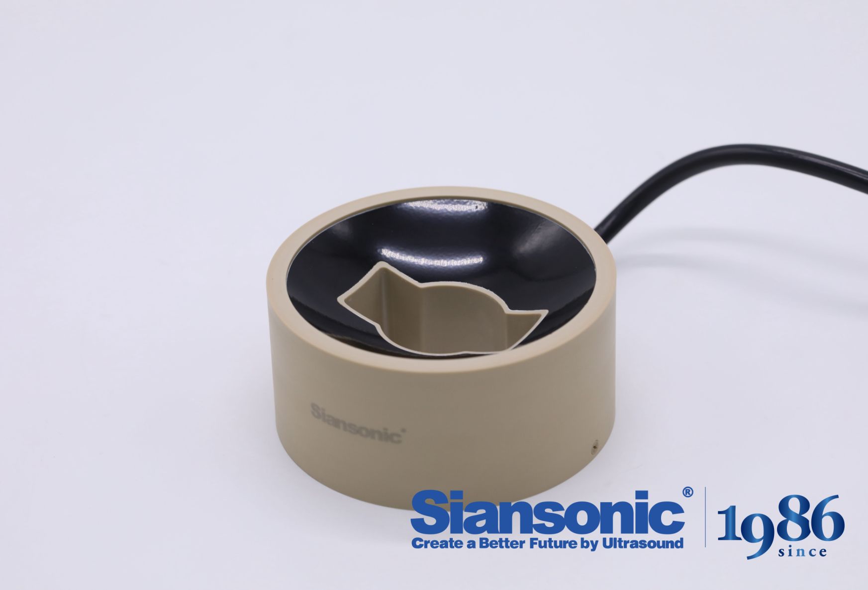
PZT ceramics have set the baseline for acoustic transducers, but their electromechanical coupling and mechanical Q leave room for improvement when a system needs tightly controlled acoustic pulses. Relaxor-based single crystals such as PMN-PT and PIN-PMN-PT push the piezoelectric strain coefficient well past what bulk PZT can offer, often reaching d33 values two to three times higher. This allows lower drive voltages for the same displacement, but the trade-off is a drop in coercive field and a more pronounced temperature dependence, which must be accounted for in continuous or high-duty-cycle operation.
Composites built from piezoelectric ceramic pillars embedded in a passive polymer matrix give engineers another lever. By adjusting the volume fraction, pillar aspect ratio, and matrix stiffness, the effective acoustic impedance and lateral coupling can be tuned away from the monolithic ceramic values. For controlled output, 1-3 connectivity composites reduce spurious radial modes that blur the main thickness-mode response, leading to cleaner ring-down and better axial resolution. The polymer phase also adds damping, which can shorten pulse length but at the cost of some absolute sensitivity.
Single crystals and composites are not direct drop-in replacements for PZT; they require different matching, backing, and bias strategies. A common approach is to pair a crystal layer with a carefully selected backing and matching stack so that the transducer's bandwidth widens without exciting harmonic distortion. In situations where thermal stability is paramount, PIN-PMN-PT crystals with higher phase transition temperatures are preferred over binary PMN-PT. Ultimately, the material choice should follow the required acoustic output envelope: peak pressure, pulse duration, repetition rate, and acceptable side-lobe levels all shift the optimum away from a one-size-fits-all ceramic.
Frequency Tuning to Match Skull Thickness and Target Depth
The human skull is far from uniform, with thickness varying across individuals and even across different regions of the same cranium. When delivering focused energy through bone, the frequency of the ultrasound or electromagnetic signal must be adjusted to account for this variability. A higher frequency tends to attenuate more rapidly in dense cortical bone, making it less suitable for thicker skulls, whereas a lower frequency can penetrate more readily but sacrifices spatial precision. This trade-off requires a tuning process that reads the local thickness profile, often obtained through imaging, and then shifts the carrier frequency so that the beam reaches the intended cortical or subcortical target without excessive energy loss or heating.
Target depth adds another layer of complexity. Even with a known skull thickness, the distance from the transducer surface to the neural region of interest changes the optimal frequency window. For shallower targets, a slightly higher frequency may offer better focusing and less beam divergence, keeping the acoustic or electrical field tight around the desired site. For deeper targets, lowering the frequency becomes necessary because the cumulative absorption along the path can otherwise starve the focus of usable energy. Practical systems often embody this as a lookup table or a rapid sweep across a modest frequency range, measuring reflected power or acoustic feedback to lock onto the frequency that yields the strongest, most confined response at the planned depth.
One effective strategy is to combine real-time thickness estimation with adaptive frequency stepping. Instead of relying on a one-size-fits-all setting, the device emits a short calibration pulse, analyzes the echo profile, and then selects a frequency that balances penetration and resolution for that specific anatomical geometry. This approach reduces the need for heavy pre-procedural modeling and accommodates natural variations among patients. The result is a more consistent therapeutic or imaging outcome, where the same nominal target depth can be reached across different skulls without manually reconfiguring the hardware for each session.
Rapid Prototyping Loops: From Simulation to Benchtop Validation for tFUS
Iterating on transcranial focused ultrasound hardware often stalls when simulation results don't match what's measured on the bench. A tighter loop starts with a simplified acoustic model that only captures the dominant near-field interactions, then runs a handful of single-element prototypes through a standardized skull phantom. Discrepancies at this stage usually point to transducer mounting tolerances or material property mismatches, not the beamforming algorithm itself.
The next cycle brings in a multi-element array with the same driving electronics intended for the final system. Here we swap the uniform phantom for a 3D-printed replica derived from CT data, adding realistic density variations and suture lines. Hydrophone scans are compared against simulation across three axial planes, and the difference map feeds directly into a revised set of boundary conditions for the next modeling pass.
Each loop prunes one source of error before moving on: first the single-element acoustic output, then the array phase alignment, and finally the effects of electronic crosstalk under pulsed operation. By the time the benchtop setup produces the intended focal spot shape and pressure range, the remaining unknowns are mostly biological, not instrumental.
Thermal Rise, Cavitation Risk, and Other Safety Thresholds in Custom Design
When a component is pushed beyond its standard envelope, thermal rise is rarely uniform. Custom geometries create uneven heat paths, and the hottest spot often sits where the designer least expects it—near a weld, a sharp corner, or a dead volume of fluid. Simply monitoring inlet and outlet temperatures gives a false sense of security. Real safety demands mapping local gradients, because a ten-degree average increase can hide a thirty-degree spike at a stressed interface, slowly degrading material properties long before a catastrophic failure announces itself.
Cavitation is another threshold that custom designs tend to disturb. Altering the flow passage, tightening a clearance, or adding a bend can drop local pressure below vapor pressure even if the overall system looks healthy. Once vapor bubbles form and collapse against the surface, they eat away metal with a distinctive pitting that accelerates under repeated cycles. Designers who ignore cavitation risk in a bespoke layout often discover it only through vibration or noise, by which point the impeller or valve seat is already compromised. A robust custom design should include a margin for NPSH that accounts for the worst-case local geometry, not just the nominal pump curve.
Beyond temperature and cavitation, there are quieter thresholds: fatigue limits from pressure pulsation, seal extrusion gaps under thermal expansion, and bearing loads when the shaft deflects under non-symmetric flow. Each of these thresholds shifts when you deviate from a proven standard. The safest custom design is not one that merely meets the specified duty point, but one that deliberately probes the corners of the operating envelope—startup transients, blocked outlet scenarios, rapid temperature swings—and verifies that no hidden threshold is breached before the first real-world run.
Patient-Specific Transducer Arrays: When Anatomy Dictates the Blueprint
The idea that a single transducer design can serve every body shape and clinical scenario collapses the moment you look at real anatomies. Rib spacing, skull curvature, breast density, even the depth of a particular organ shift from patient to patient. A transducer array built around a generic model might perform beautifully on a phantom yet deliver poor acoustic coupling or distorted wavefronts on an actual person. This is why patient-specific designs are moving from research curiosity into practical necessity, especially for procedures where precision hinges on matching the array's geometry to the tissue it faces.
When anatomy dictates the blueprint, the design process flips. Instead of starting with a standard piezo element pitch and frequency, engineers begin with imaging data: CT, MRI, or ultrasound scans that map the target region. From there, the array's footprint, curvature, and element distribution are tailored so that the beam focuses where the clinician needs it, not where a one-size-fits-all lens assumes the organ should be. This approach doesn't just improve image resolution; it reduces the energy required to penetrate irregular tissue layers, which in turn lowers heating and side-lobe artifacts. In cardiology, for example, a patient with an unusually rotated heart benefits from an array whose elements follow the actual intercostal windows rather than fighting them.
The real shift, though, is in how quickly such custom arrays can now be produced. Additive manufacturing of piezoelectric composites and flexible circuit interconnects has shortened turnaround from months to days. A clinician can upload a segmented anatomical model, adjust the array's conformal surface in software, and receive a transducer that fits that patient's specific acoustic window. It's no longer about forcing the body to match the tool; the tool now grows from the body's own geometry. That inversion is quietly rewriting the rules for therapeutic ultrasound, guiding interventions, and even long-term monitoring implants where comfort and stability depend on anatomical conformity.
FAQ
A tFUS transducer is a device that emits focused ultrasound waves through the skull to stimulate specific brain regions. Unlike diagnostic probes that produce broad beams, it's engineered to concentrate acoustic energy into a small, controllable spot. Custom designs often involve phased arrays or shaped elements to compensate for skull distortion.
Off-the-shelf transducers usually come with fixed frequencies, focal lengths, and aperture sizes. That limits where you can target. A custom build lets you match the geometry to your specific target area, skull thickness, and stimulation protocol—critical for animal models or unusual human skull variations.
Before fabricating anything, researchers typically run acoustic simulations using CT or MRI data of the skull. These models predict how ultrasound waves bend and attenuate as they pass through bone. The transducer's element layout and driving phases are then iteratively adjusted so the focus lands precisely where intended.
Frequency, aperture diameter, and element pitch. Higher frequencies produce a smaller spot but attenuate more quickly, limiting depth. A larger aperture can focus deeper and tighter, but the skull's irregular surface makes phase correction harder. The number and arrangement of elements also determine steering range.
Two common approaches: use a phased array with time-reversal or phase-aberration correction, or design a physically shaped lens/mirror matched to an individual's skull. Custom transducers often combine both—measuring skull thickness from imaging and adjusting each element's phase so waves arrive in sync at the target.
Piezoelectric materials like PZT or single-crystal PMN-PT for the active elements, backed by tungsten-loaded epoxy to dampen ringing. Matching layers made of graphite or parylene improve acoustic coupling. For the housing, 3D-printed biocompatible resins or machined aluminum are common, depending on whether it's for acute or chronic use.
You need to verify acoustic output power, focal intensity, and mechanical index. Thermal safety is checked with MRI thermometry or thermocouples in phantom models. Also, cavitation detection systems are often integrated to shut down stimulation if microbubble activity becomes excessive. Institutional review boards typically require these tests before any human pilot study.
Conclusion
The push toward custom tFUS transducers marks a shift from off-the-shelf piezo discs to devices shaped by the skull and target anatomy themselves. Rather than accepting a standard flat aperture, designers now vary element curvature and boundary contours to tighten the focal volume, reducing off-target energy deposition in superficial cortex. This geometric freedom only becomes useful when paired with materials that do not behave like conventional PZT. Single-crystal piezocomposites and relaxor ferroelectrics offer lower acoustic impedance and higher electromechanical coupling, allowing the same drive voltage to produce a cleaner, more predictable pressure field. Frequency selection then acts as a tuning knob. Thicker temporal bone calls for lower carrier frequencies to limit attenuation, while deeper subcortical targets benefit from slightly higher frequencies that restore focal gain. These choices rarely survive first-pass simulation, so bench testing with hydrophone scans and skull phantoms feeds back into iterative design within days, not weeks.
Safety is not an afterthought in this workflow. Custom arrays require patient-specific thermal modeling because irregular skull curvature creates hot spots near the diploë and suture lines, even when the intracranial focus looks benign. Cavitation thresholds shift with frequency, pulse duration, and the presence of standing waves from reflected paths, so designers build in real-time cavitation detectors rather than relying on fixed mechanical indices. When anatomy dictates the blueprint, as in patients with previous craniotomies, bone flaps, or asymmetric ventricles, the array is no longer a generic bowl. Element placement, normal vectors, and even local matching layers follow the individual CT-derived skull map. The result is a transducer that treats the brain as an anatomical problem to be solved, not a standardized volume to be aimed at.
Contact Us
Contact Person: Ivy Zhang
Email: [email protected]
Tel/WhatsApp: +86 1081502288
Website: https://www.siansonic.com/